[ad_1]
Credits: This story was originally published on ch00ftech and reprinted with written permission from the site owner. All media provided by ch00ftech.
Background and motivation
It should come as no surprise that I really really want a Tesla. Or really any Electric Vehicle for that matter. The only problem at the moment is that my daily commute takes me 20 minutes on foot each way, so I really can’t justify buying a car that will spend most of its life parked in a garage or parked in Seattle traffic.
That’s why I have to live vicariously through other people, and why I got super excited when I learned that my dad put down a deposit on a new Model S.
It hides it well, but the Model S is a massive car with a length of 196 inches and a weight over 4700 pounds. My dad originally planned on parking the car in his driveway, but when it came time to install the charging port, he opted for the garage instead. The only problem was that his garage only offers about six inches of clearance to be shared between the front and back of the car.
This predicament gave me some great gift ideas. With the holidays fast approaching and all of the other projects that I wanted to finish before heading home, I originally did a quick Amazon search for ultrasonic parking sensors. Sadly, most of them “bottom out” at a fairly reasonable one foot. I couldn’t find any that would drop to the two to three inch range.
So I added another project to my list and got to work!
Sensor
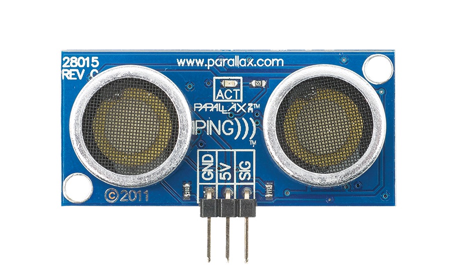
Step one was acquiring an ultrasonic sensor. As it happens, I had one of these handy:
A few years ago, I acquired one of these while trying to make an ultrasonic early warning collision system for smartphone users who are too engrossed in their Twitter feed to watch where they’re walking. That project didn’t go anywhere…
The PING))) sensor works like most ultrasonic sensors by producing a high frequency sound and waiting to hear it bounce off something and return. Interfacing with it consists of providing an electrical pulse on the signal line after which it will produce a single square wave whose width roughly corresponds to the duration between sound transmission and reception.
The PING))) sensor is super easy to use, but the form factor wasn’t going to work for something that I eventually wanted to fit into a phone case. I also felt like I should build one from scratch considering that I write a blog about how I make things.
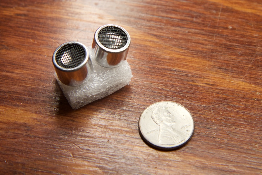
I never did manage to build one from scratch, but I did go far enough to order some 40kHz transducers:
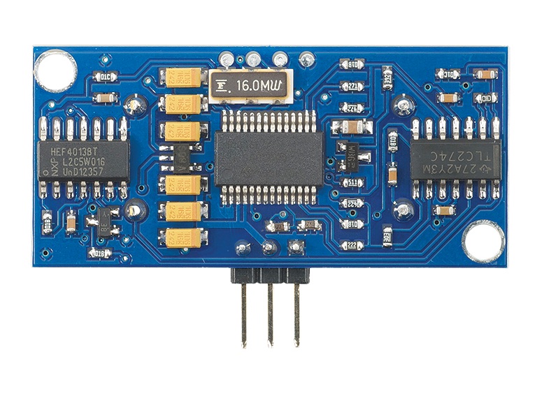
and begin a moderate teardown of the sensor:
When it came to making a parking sensor for my dad in just a few weeks, I didn’t have enough time to fulfill my original goal of building one from scratch, so I ultimately used the PING))).
That being said, there’s still some interesting things that I learned from the teardown regardless of how incomplete it is, so I thought I’d take some time to interpret my two-year-old notes and share some of those learnings with you.
Teardown
I don’t even have one of these things on hand at time of writing, so apologies if this teardown is mostly incomplete. The board contains a multi-gate opamp, a charge-pump inverter, a flip-flop, and a micro controller. You can make out the part numbers for the flip flop and opamp from the image above, but I didn’t record the others.
TRANSMISSION
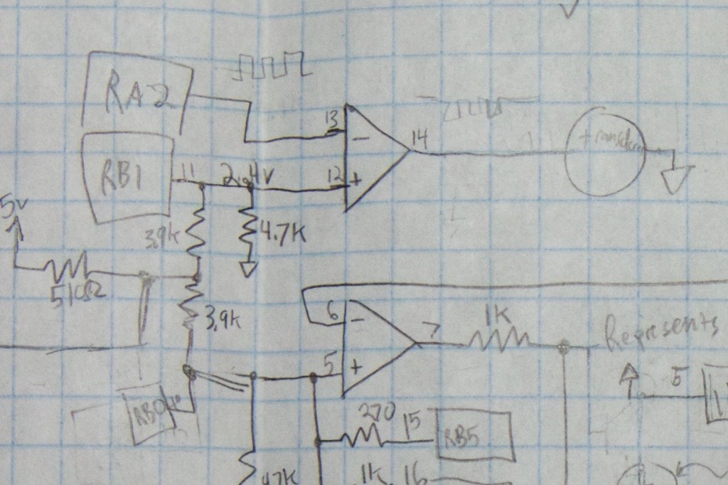
Step one is driving a transducer at 40kHz. All of the audio circuits on the board use a large multi-gate op-amp (TLC274C) which is powered from the 5V rail and a -5V rail generated by the charge pump inverter.
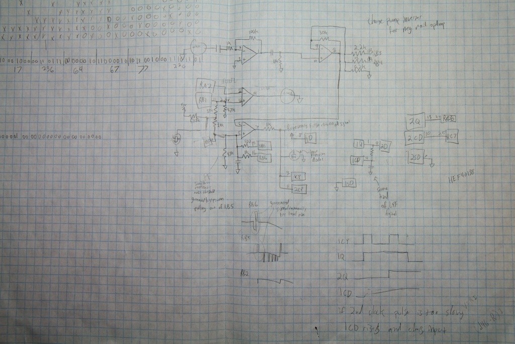
(Throughout this schematic doodle, I use “RA_” or “RB_” to describe GPIO pins going to the micro controller)
So at the basic level, RA2 produces a 40kHz square wave on the inverting input of the opamp while the non-inverting input floats at about 2.4V. This produces a 10Vpp square wave which drives the transducer.
The 3.9k resistors produce the half-rail (2.4V) DC voltage, but I’m still not sure what RB1 and the rest of the passives have to do with it. It’s possible that they serve some purpose in muting the transducer, but it’s not clear.
RECEPTION AND FILTERING
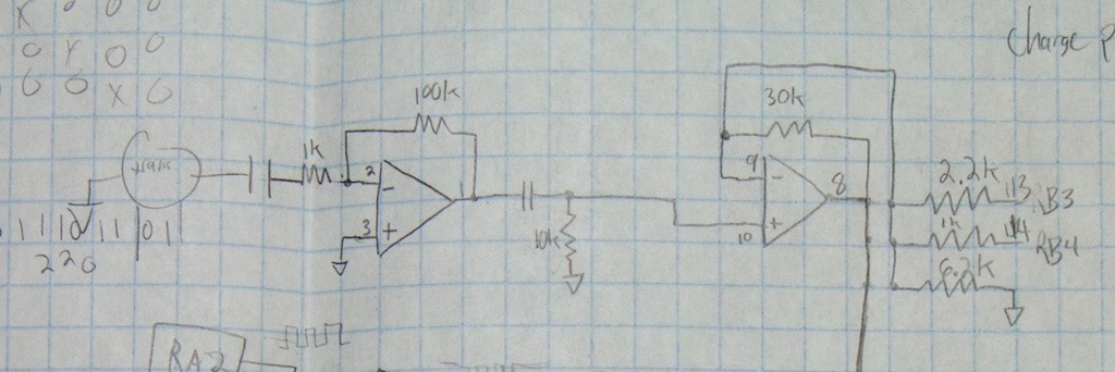
On the receiving side, the receiving transducer’s output passes through a DC blocking diode and then through an inverting amplifier with a gain of 100. It then passes through a high pass filter with an unknown cutoff frequency (didn’t measure the capacitor), but I’m assuming it cuts off everything in the audible range and then some.
Next is a non-inverting amp, but this one has a software adjustable gain. If RB3 and RB4 are left floating, the gain is 5.8, but by pulling both pins down to GND, the gain can go as high as 49. I’m assuming that whatever micro controller they used has a decent tolerance for negative voltages on the GPIO pins since this signal is ground biased and could potentially swing pretty far in the negative direction.
AMPLITUDE CHECK
The next part of the circuit I found particularly clever. When trying to pull a signal out of noise, it’s often important to have a “squelch” level. This is the minimum amplitude required for a signal to be considered a signal and not just noise. Ideally, this squelch threshold should be set as close to the intended signal level as possible in order to cut out the most noise.
This can easily be accomplished with a fixed threshold, but the problem is figuring out where to set it. As the ultrasonic signal travels away from the PING))) sensor, it spreads out which means that the signal reflected off distant objects will be much weaker than the signal reflected off nearby objects. You could set the threshold for the expected amplitude of the most distant object you expect to see, but then you’re opening the gates for more false-positives generated by noise.
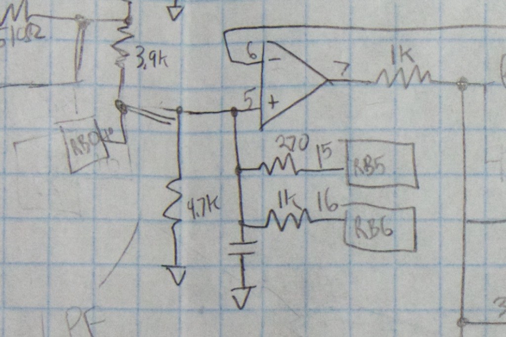
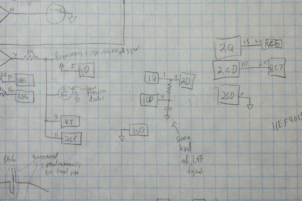
The PING))) sensor solves this problem by having an adjustable threshold that drops while the signal is in the air. After it’s filtered as shown above, the signal is passed to the inverting input of another gate of the opamp which is configured as a simple comparator:
This isn’t terribly interesting by itself, but RB5 and RB6 do some cool stuff when the device is activated:
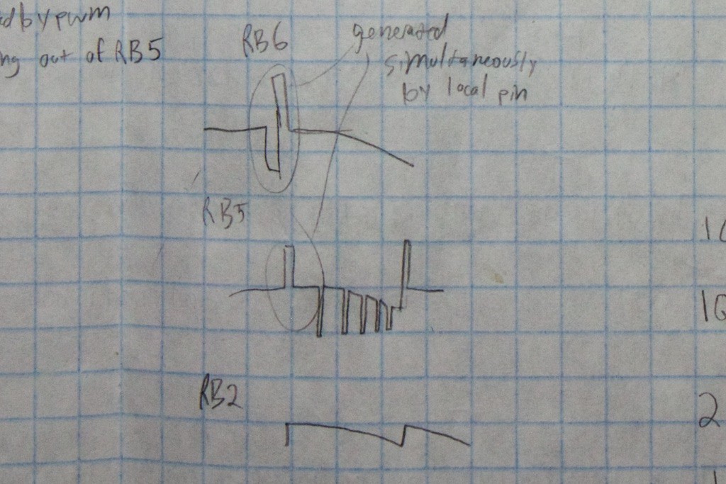
When the signal is first released, RB5 and RB6 pull up the voltage on the capacitor. Then, over the next few milliseconds, a series of open-drain pulses on RB5 lower the voltage on that cap and reduce the threshold going into the comparator/opamp. This effectively allows the processor to do some analog signal processing without the use of a slow ADC or DAC. I’m assuming that tuning this process to work just right involved a lot of trial and error which could explain some of the extraneous processor pins and passives that don’t appear to do much in the final application.
DIGITAL HIGH-PASS FILTER
At this point, we should hopefully have a square-wave reproduction of our original 40kHz signal coming from the output of the comparator. As one final check, the PING))) looks for two sequential signal edges coming roughly 1/40,000th of a second from each other. This is accomplished with a pair of flip-flops.
My doodle of the schematic here is a little gross, but there are immediately some interesting things to note.
Firstly, after passing through a 1k resistor, the signal connects to some unknown three-terminal SOT23 device. Strangely, only two of the three terminals of this device are connected (one of the other terminals connects to ground). Given that the comparator is powered by a positive and negative rail, I’m assuming that this device acts as a protection diode which prevents the signal from going too far below ground. This way it won’t blow up the flip-flop. The 1k resistor keeps the current within reason.
Next up, the signal passes to the clock pins of two flip-flops contained within the HEF4013b. With this configuration, when the signal goes high, the input of each flip-flop (1D, 2D) will be passed to the output (1Q, 2Q). Because 1D is connected directly to the positive rail, 1Q will go high along with the first rising edge of the signal.
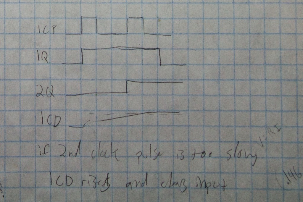
The output of the first flip-flop (1Q) is connected to the input of the second (2D) which means that the output of the second flip-flop should also go high with the second clock-edge. But there’s a clever bit to it. The output of the first flip-flop is also connected to a simple low pass RC filter which drives 1CD, the clear bit of the first flip-flop. The resulting waveforms look like this:
With this configuration, 2Q (and therefore RC6 on the processor) will go high with the second pulse of the signal (1CP), but if the second pulse doesn’t come quick enough, eventually the capacitor on 1CD will rise high enough to trigger the reset of the first flip-flop and start the process over.
PING))) CONCLUSION
With these filters, the only way to get a clock edge on the RC6 pin is to have two consecutive clock edges of a signal at least 40kHz in frequency and of an appropriate amplitude. Anything else will reset indefinitely until the processor eventually gives up and sends out another ping.
When I originally set out to build my own sensor, I thought I’d be doing a lot of work with DSPs, but I quickly found out exactly how difficult it is to process 40kHz audio when most ADCs are built for audio applications and are therefore primarily for the audible frequency range. I thought it was pretty clever how the PING))) uses several simple analog circuits to do some rudimentary audio processing without the use of a costly high speed ADC.
Schematics
After electing to use the PING))) sensor exactly as directed, I needed to build the rest of my circuit. I wanted to build something robust that would mount nicely on the wall of my dad’s garage. Figuring that the sensor would likely need to be placed down low by the car’s bumper, I decided on a two-component design consisting of a small sensor and a large visible display that could be mounted at eye-level.
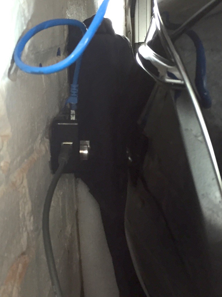
I opted to use USB for power and ethernet for connecting the two parts of the system. This would allow the maximum level of flexibility with mounting.
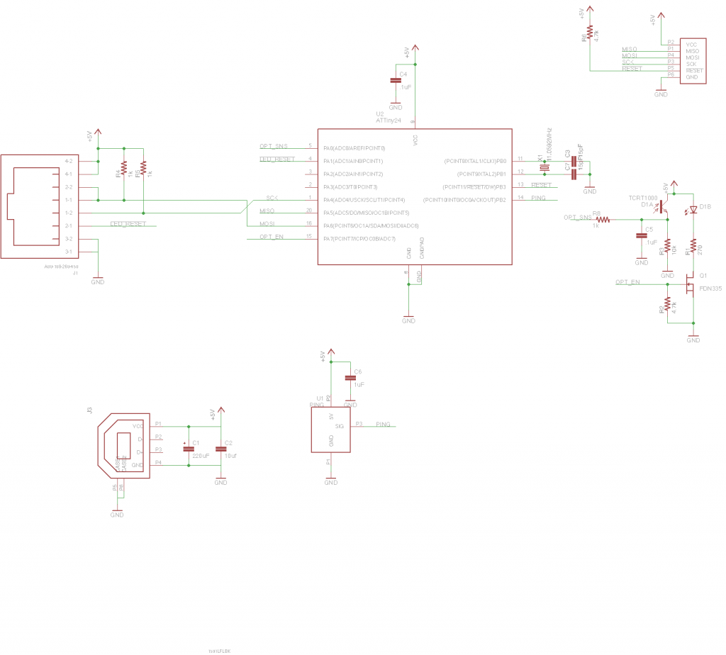
The schematic for the sensor is as follows:
There’s not a whole lot to talk about here. The sensor simply has hookups for USB and the PING sensor with an ATTiny24 running the whole show. Going to the ethernet jack is 5V and GND rails along with the I2C bus. I2C isn’t designed for transmission over long distances, but I wasn’t in the mood to configure a proper RS485 interface. I decided to lower its impedance by using some really strong pull-ups and cross my fingers that it wouldn’t couple on too much noise from the power rails.
When I set out, my primary concern was that the ultrasonic sensor would not be able to detect the car when it got really close, so I also included hookups for an infrared proximity sensor that I could potentially use.
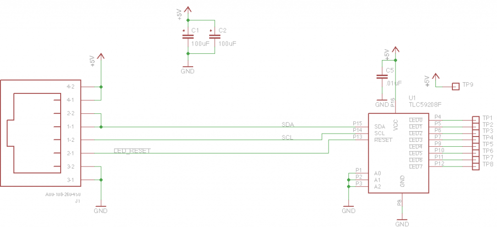
On the other side of the ethernet cable is the display driver which consists of a single TLC59208F. This I2C controlled LED driver can control up to 8 LEDs with 8 bits of brightness using its open-drain outputs allowing for 256 different brightness levels per channel. It accomplishes this with a 97kHz PWM that it maintains entirely on its own. This greatly simplified what my processor needed to do and offered a lot of flexibility should I want some fun pulsing LED animations.
Due to the size of my sign, I opted not to solder the LEDs directly to the PCB in order to cut down on the amount of PCB required. Instead, I simply air-wired them between the 5V rail at TP9 and the appropriate drain pin in series with a current-limiting resistor. To simplify the design, I could have used the TLC59108 which includes current limiting elements, but at the time, I wasn’t sure if I wanted to do two LEDs in parallel for each channel and that would require two separate current limiters as you may already know.
Mechanical build – sensor
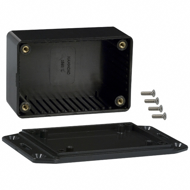
While the bar graph display was meant to be the “eye-candy” of the project, I still wanted the sensor package to look a little more legit than some of my more haphazard projects. For this reason, I shopped around for an enclosure that had some mounting features to make it easier to affix to a garage wall. I settled on the 1591LFL from Hammond:
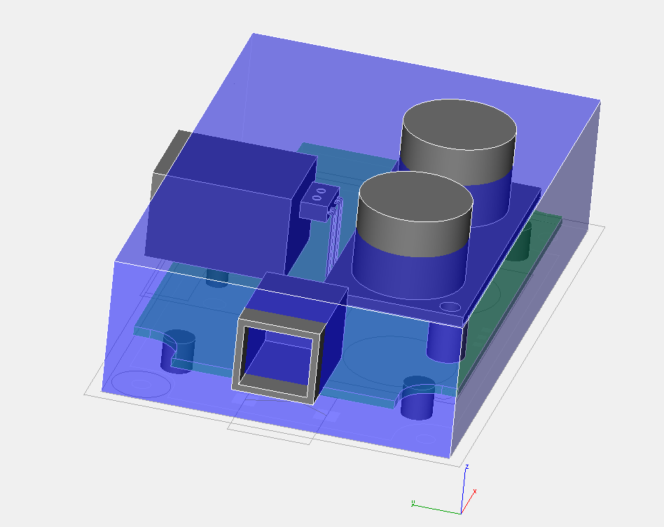
Although this enclosure didn’t come with the usual PCB outline that I’ve come to expect from Hammond, it did have enough details that I could mock up a PCB outline and a quick 3D model in ViaCAD to make sure everything would fit:
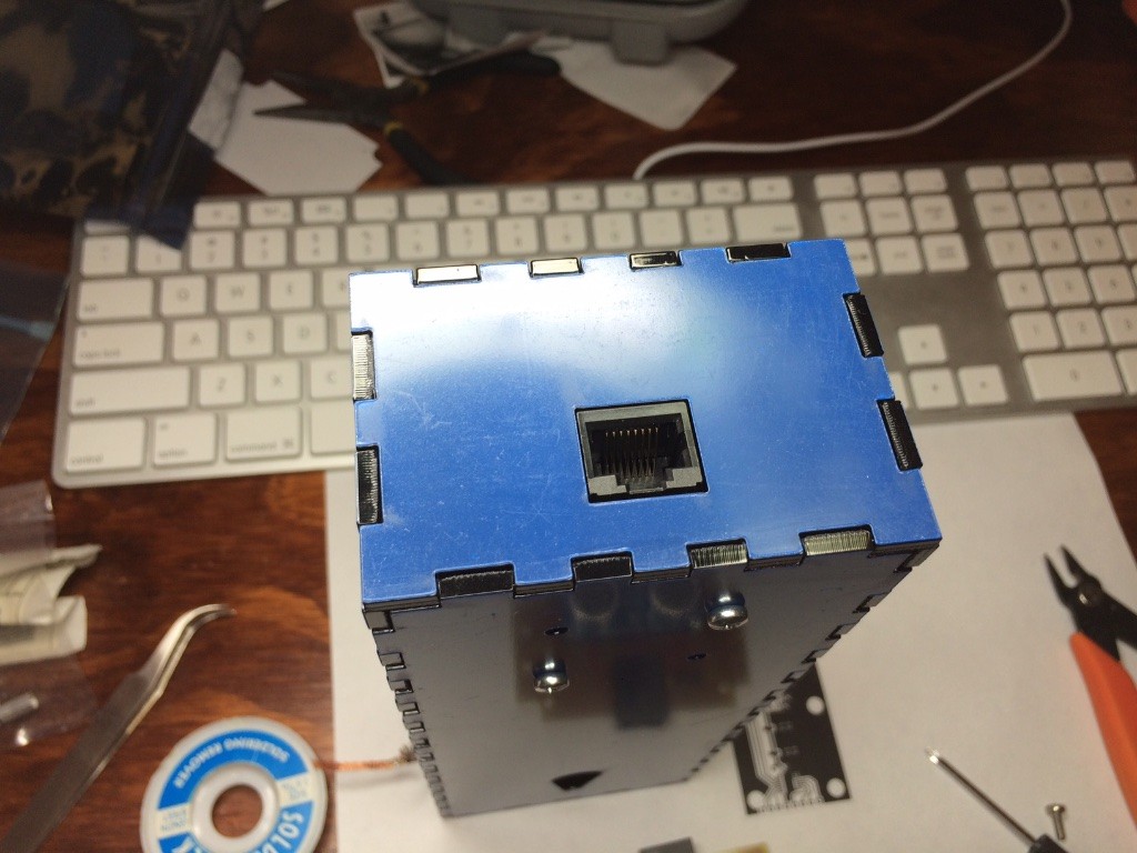
Here you can make out the transducers of the PING))) sensor poking out the front along with the USB port on the left side and the ethernet port coming out the top. I also mocked up the IR proximity sensor in the middle. I figured I’d have to cut a little window for it, but ultimately I didn’t need the extra sensor.
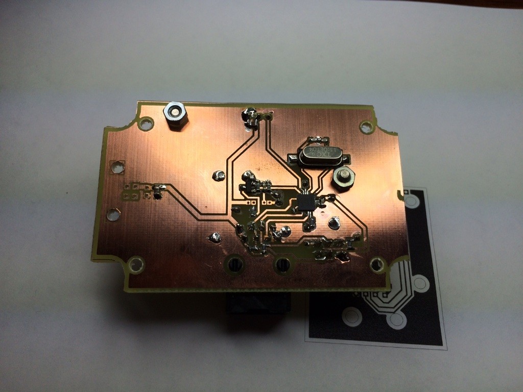
All put together, the PCB looked like this:
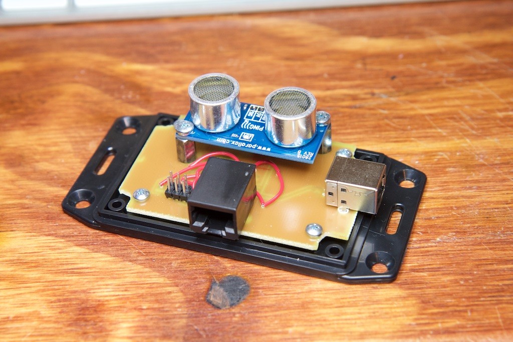
And when mounted to the back plate of the 1591LFL with the recommended 1593ATS screws (sold separately), it looked like this:
The PING))) board itself is mounted with some 6mm standoffs, and I replaced its included right-angle 0.1″ header with a straight header to allow it to connect to a mating female header soldered to my PCB.
Next was the trouble of getting the lid to fit. This would require cutting some holes around the sensors and ports.
This was a job for a CNC mill.
Getting two components to fit together nicely is something that I’ve attempted a few times with moderate results. I usually overestimate the amount of clearance needed around the parts to allow them to fit. This time around I decided to really push it and give myself just a quarter millimeter of space around the edges.
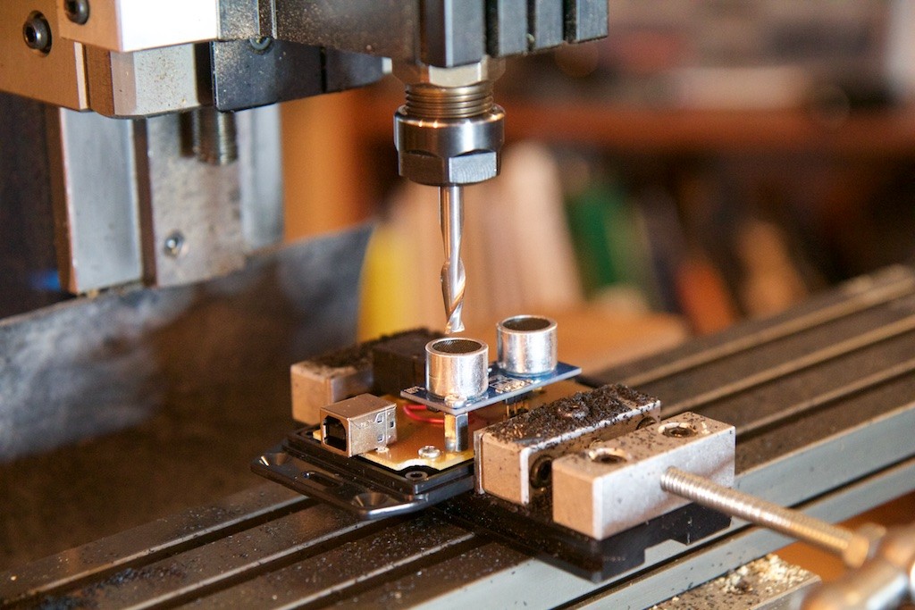
About 90% of any CNC job is proper fixturing, so I used some parallels and a vice to hold the box on its side for the USB and ethernet port cuts:
These were fairly straight forward cuts. I used an edge-finder to zero the CNC head on the edges of the box and simply cut a rectangle in the appropriate spot with a 1/16″ end mill.
The transducer holes were really no different, but because of the tolerance stack-up of the PING))) and my mounting paranoia that I’d screw something up, I did a pre-alignment with the bottom half of the enclosure:
and simply removed the PCB and held the top of the box down for the actual cut.
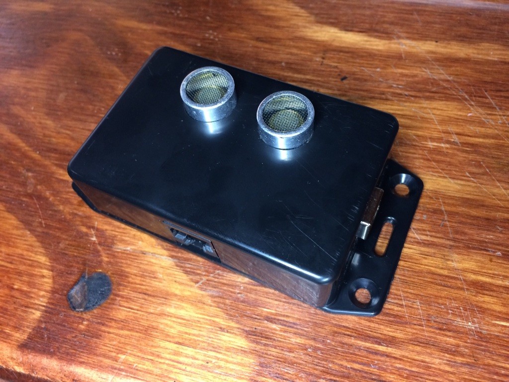
The results were…really amazing:
I have never in my life gotten something to fit together this well. There’s a barely perceptible gap around the transducers, and there’s even a tiny bit of friction on the sides of the ports as you lower the top down. It really feels solid.
Now for the eye-candy.
Mechanical build – display
While prefabricated enclosures are really easy to use, they tend to get expensive when things get really big. I wanted my sensor display to be super big and visible, so I decided to build it from scratch using some sheets of acrylic. This also afforded me the ability to get a nice glossy black finish to match my dad’s car.
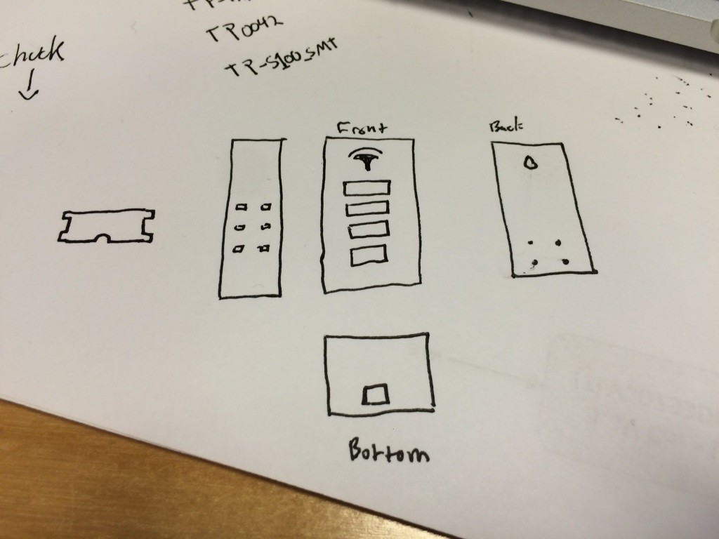
I quickly sketched out a rough design:
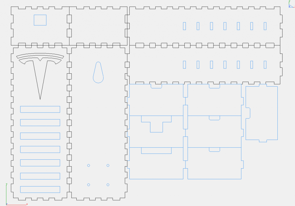
After settling on some arbitrary dimensions, I went to makercase.com. This site makes it super easy to get plans for building boxes out of laser cut materials.
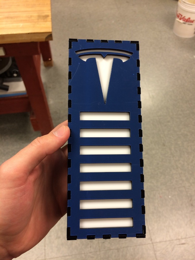
After adding some features to the makercase design, I had this:
The plates on the bottom-right are designed to sit between the illuminated bars to keep them separated, and they even have a cut out for the driver PCB and the wires going to the LEDs. I also included a 1/8″ gap between the separators and the front plate so I could add another piece of acrylic to diffuse the light.
I was a little concerned about the separators because I didn’t know how much of a gap I needed to leave in their mating holes for them to fit together nicely. I took some measurements from the maker case plans and estimated that I needed about 0.001″ gap on either end of the slots. I’m not sure if this gap is crucial since the laser will tend to melt the acrylic and cause the edges to recede slightly, but it certainly didn’t hurt.
Not bad!
My original design had the full Tesla logo with the text and everything, but the small features of the text proved too delicate for the laser cutter which melted and deformed them.
The acrylic comes with a protective blue layer that you’re supposed to peel off. I waited until the last minute to peel it off and forgot to get a picture, but you can use the video at the top and your imagination to figure out how it looked.
Next up was fitting all of electronics inside:
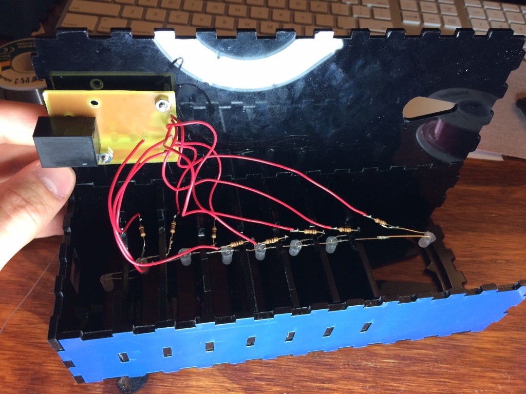
I carefully drilled some holes in each of the separators and used them to support the LEDs. The whole wiring job was pretty straight forward though getting the box to shut without getting the wires stuck between the separators and the back was a royal pain. If I had more time, I would have spent some of it simplifying the wiring because this seriously took 10 minutes every time I wanted to open up the box.
Now that’s a snug fit! The whole box fit together pretty snugly in fact, so I held off on gluing it until I was 100% certain that it worked. When the time came, a few careful drops of cyanoacrylate (super glue) did the trick.
Firmware
I specifically chose the ATTiny24 for this design because of its included I2C (or as everyone but Phillips likes to call it “TWI”) port. I’ve used I2C before, so I was looking forward to using the port to program and control the LED driver. After I went through all of the effort of building the PCB, I was a little scared to find that there were no commands to control the I2C port!
Some googling revealed that the ATTiny24 includes the necessary link-layer bits to make I2C work, but the protocol layer stuff like ACKing and NAKing needs to be handled by the firmware. Not looking to write my own I2C driver from scratch, I googled a little more and came across a driver provided by Atmel (it’s on this page under AVR310). It took a few tweaks to make it work on the ATTiny24 (the example was written for a different device), but within a short amount of time, I had my display up and running:
Next up was driving the PING))) sensor. In order to get the best level of precision in the critical time-of-flight measurement, I used an interrupt to trigger both the start and stop of Timer1.
Rather than mathing out the proper time of flight of the signal, I just played around with the 8 thresholds for the 8 bars of the display until I found something that felt right. I wanted the display to operate with a higher level of precision as the car approached the critical final inches, so I placed those thresholds closer together. The final threshold pushed the limits of what the PING))) can do and settled at roughly 1.5 inches.
When active, the sensor is programmed to take a measurement about 10 times a second. When all 8 bars are illuminated (car is parked) or no bars are illuminated (car is missing) for about 15 consecutive seconds, the display shuts off and the sensor drops into a standby mode where it only takes a measurement every few seconds.
There really isn’t much else to say about the firmware. I invite you to download the project files if you’d like to know more (though good luck navigating the comments. I wrote the whole thing in about an hour).
Results and adjustments
My dad was super stoked as soon as I showed him the sensor. He had already mounted a rubber padded mat to the wall, and installed one of these:
But the ultrasonic solution had a level of sexiness that really fit well with the car.
Even though my sensor could get the car much closer than the off-the-shelf options, I was still concerned that I wasn’t close enough. It turns out that I actually had the opposite problem. The sensor was letting the car get a little too close! With its all-electric drive, the Tesla has remarkably precise control at low speeds, but even still parking a car day-in and day-out within two inches of a target under penalty of scratching the paint is a little much to ask. The video above was taken under these conditions, and you can see a little bit of apprehension in the last few inches.
I mean, it’s damn close:
So I reprogrammed the sensor to roughly double the target distance and all was well. The T lit up brilliantly, and the car still had enough room on each side to fit in the garage. Curiously, simply doubling the threshold value didn’t double the target distance. Even with my interrupt-driven solution, there’s still enough processor overhead in the 300μs or so measurement that moving from 1.5″ to 3″only took a change from 25 to 29 ATU (arbitrary time units). I never did figure out where this offset came from. My micro controller was only running at 1Mhz, but that should still be fast enough to service a routine in well under 300μs. I’ll leave that one as an Exercise To The Reader.
Conclusion
So this was a refreshingly trouble-free ch00ftech project. I’m on a roll this year! Still, I learned about making project enclosures with a laser cutter and I got some good experience making some precise cuts with my CNC as well. Also, if I ever do want to make that phone collision detector, I’ve got a good head start!
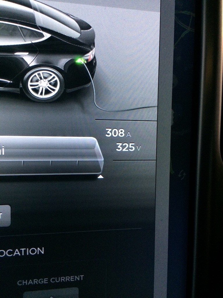
Bonus charging pic:
Download the files for this project here: Parking Sensor v1.0
Credits: This story was originally published on ch00ftech

[ad_2]
